The Bending Equation and Tensile and Compressive Stress
When tightening a nut a force is applied and the nut will move. The turning effect of the force is called the moment of force or a moment. The size of this moment depends on two main factors.a) the size of the force acting at right angles to the shank.
b) the perpendicular distance between the point of application of the force and the centre of the nut.

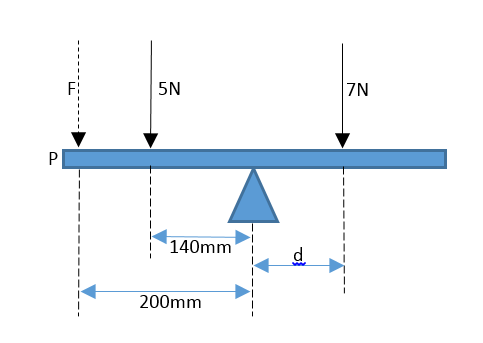
Giving notice to the figure above, the moment M of a force acting about a point P is force x perpendicular distance between the line of action and the force.

Equilibrium
If more than one force is acting on an object and the forces do not act at a single point then the turning effect of the forces, that is, the moment of the forces must be considered.

Above is a beam being vertically supported at point P with forces acting downward (F) on either end. A beam is said to be in equilibrium when there is no ability for it to move due to unequal forces acting on it. There are two conditions for equilibrium to be in action:
i) Force acting up must equal forces acting down,
Rp = F1 + F2
ii) The sum moment of the forces acting on a beam must equal 0.
the sum of the anti clockwise moments and the clockwise moments
must equal each other.
This statement is known as the principle of moments and by taking moments in both direction equilibrium can be calculated.

Therefore :


Bending a Material
Bending materials is an important concept to understand especially if you intend on building a frame or support that is going to be load bearing. There are many forces that act upon a 'beam' and to understand what forces are acting where helps to understand what is happening at a molecular level.
Consider a rectangular solid section that has started to sag in the middle.

Imagine there are bands throughout the bar for which you are measuring the forces, the top half of the bar is in compression, meaning the force is acting down on the beams centre line. Under this line the bar is in tension, the forces are stretching through the bar. the greatest stresses will occur at the outer edges of the beam. The stress levels will reduce uniformly through the material until the centre line is reached, at this point, where the stress changes from compressive to tensile there is no direct stress. This is referred to as the neutral axis and for any symmetrical section this is considered to be mid depth.
The rectangular beam is not always the best application when heavy load is being carried. This is because the greatest stress is on the outer fibres. An I beam is designed so that the to and bottom flanges resist the tensile and compressive forces and the cross section resists the shearing forces.
If the beam was to bend the other way, such as an aircraft wing would bend one way then the other, then the top of the beam would be in tension and the underside is in compression.
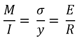
The stress in the material is proportional tot he distance from the neutral axis. This is known as distance 'y', hence the stress at a distance y from the neutral axis is such that

Therefore:

or


When the beam is loaded, the bending moment applied, represented by 'M' is resisted by an equal internal moment. This can be written as

Where I is the second moment of area of the beam section about the neutral axis.

Assumptions
The bending moment equation is based on certain relationships between different quantities such as stress, elasticity, curvature and dimensions. For these relationships to be valid the following five assumptions need to be made.
1) The bending equation assumes Hooke's Law on each layer of the beam and Young's modulus has the same value in compression as in tension.
2) The beam material is uniform throughout.
3) Each cross section of the beam is symmetrical about the plane of bending and the loads are applied to the beam in the plane of bending. If a horizontal beam supports vertical loads then the plane of bending is vertical.
4) The beam was initially straight and unstressed.
5) The resultant force perpendicular to any cross section is 0.
More will be added to this page in the near future, please keep returning.
No comments:
Post a Comment