Stress and Strain

This may not be something that you would consider when looking at automotive engineering but materials are very important. When designing an engine, the chassis or even the body panels, the materials used will determine the efficiency, reliability and usability of the vehicle. This page is going to discuss the calculations that are used when considering what materials should be used. You are going to learn about stress and strain and the different versions of each, how they relate together and also remind yourself or direct your learning to the other pages related to materials.
A force exerted on a body can cause a change in either the shape or motion of that body. Force is measured in Newton's [N] This change on the body is due to no material being perfectly rigid and even though the changes (deformations) are not always visible to the human eye there is the ability to deform.
Take for instance a spanner as it tightens the nut on the engine. It will bend slightly, sometimes noticeable to the user but most of the time it will not. If the correct tool is used for the job then the bending action occurring on the spanner will not be permanent and the elastic region of the material will not be exceeded and the spanner will return to its original shape.
There are three main types of mechanical force that acts upon the material and they are going to be discussed on this page. They are:
Tensile Compressive Shear
Tensile Force
Tensile forces stretch the material. Wires are used to tensile forces. But in automotive applications the humble bolt is probably the most tensioned item. The length of the material will increase when under tension and if stretched beyond the elastic limit will be permanently deformed.
Compressive Force
When a material is in compression it is being squashed. There is a heavy load being placed on the material and this can decrease the length of a material. Structures such as bridge pillars, suspension springs, the jib of a crane are all in compression.
Shear Force
Where tensile and compressive forces are acting in one direction, either towards each other or away from each other, shear force is acting in two directions. Shear is a force that slides on one face of a material. Imagine rivets that are holding two sheets of metal together. If a tensile force or compressive force was to be applied to the two sheets then the rivet would be in shear. A shear force can cause a material to bend, twist or slide.
Stress and strain both have their own SI symbol
STRESS

A material is said to be in a state of stress when forces acting on it cause a change in the dimensions. Stress is the ratio of the applied force to the cross sectional area of the material. It is measured in Pascals and 1Pa = 1Nm. The cross sectional area is 90 degrees from the direction of the force when considering compressive and tensile forces but in shear it is parallel to the direction of the force.
STRAIN

Strain is the fractional change is dimension of the material that has been produced by forces acting on the material. Strain is a dimention-less and often expressed as a percentage.
Shear Strain is denoted by the Greek letter 'gamma'

The properties of direct stress and strain can be written in the following relationships.


When using these equations you need to assume that the material being calculated remains in the elastic region and is obeying Hooke's Law.
Reminder
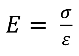
Young's Modulus
This is the relationship of stress and strain and is known as the Modulus of Elasticity. This is the resistance of a material to tensile and compression forces.
Hooke's Law
The extension of a material is directly proportional to the force acting upon it. This only works if the elastic limit is not exceeded. For example, a spring loaded with a weight, if the force of the weight does not stretch the spring beyond its elastic limit then the spring will return to its original resting position once the weight is removed. If the weight is to heavy then it will not.
Shear Stress
If a material is subjected to two forces that are equal, opposite and parallel a shear action is developed as in the figure below.

As the forces are not direct, there will be a tendency for one part of the material to slide or 'shear' from the other part. The cross sectional area under shear stress is measured parallel to the line of action of the forces:

Shear Strain
Strain takes place in the shear mechanism but deformations take place as follows:

The square face ABCD is deformed to parallelogram AB'C'D as in figure 2. Shear strain is then defined as the movement of the faces in the direction of the force divided by the distance between the faces. BB' is usually denoted by 'x' and AB by 'L'
The relationship between shear stress and strain is called the modulus of rigidity and has the quantity symbol G.

EXAMPLES
Have a go at the questions yourself before reading the answers, that way you will be able to build up your confidence..
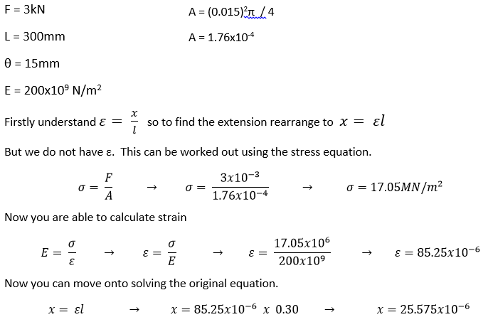
a) A mild steel engine bolt when correctly tightened provides a tensile load of 3kN. The bolt is 300mm long and has a diameter of 15mm. Given that for mild steel E = 200x109 N/m2 calculate the stress on the material. How much would the bolt extend?
b) A steel pivot bolt in a suspension arrangement has a maximum allowable shear stress of 60MN/m2 and a diameter of 25mm. Find the maximum shear force that can be applied to the pivot.

c) A nickel steel gudgeon pin in an engine piston has an outside diameter of
27mm and an inside diameter of 20mm. The
force on the piston is 8kN. The modulus
of rigidity for the steel is 90GN/m2. Calculate the stress and strain in the
material.

More will be added to this page in the future so please keep returning.
No comments:
Post a Comment